26+ i2c protocol block diagram
I2C Controller Block Diagram and System Integration 213. This architecture contains I2C slave and APB master.

Pin On Atmega328 Analogue I O Port Expander Using I2c Bus
Detailed information about the architecture of the I2C module is in Section 2.

. Protocol Details and Standards Compliance 2042. Ad DLL for creating your own I2C and SPI applications. Problem is theres no way to even retrieve those missing bytes without following protocol since bytes of a block cant be directly addressed one command of 11 characters is 0x20 the next command of 8 characters is 0x21.
I2C is a Multi-point protocol in which a maximum up-to 128 peripheral devices can be connected to. Download scientific diagram SPI bus protocol model block diagram from publication. 13 Functional Block Diagram A block diagram of the I2C module is shown in Figure 1.
The below I2C protocol timing diagram gives a clear idea of the working of the protocol. JTAG-AP FIFO Buffer Access and Byte Command Protocol 734. This way of processing the I2C protocol by the hardware peripherals reduces the work of the CPU and makes the software design easier.
Ability to read and write I2C EEPROMs using user-friendly software. Introduction to I2C peripherals of STM32 STM32s I2C. Scan Manager Address Map and Register Definitions.
There exist a few communication protocols such as UART communication I2C protocol and SPI Serial Peripheral Interface protocols. I2C Primer is the. BLOCK DIAGRAM The communication bridge between I2C and APB is shown in below figure.
Today this article let us understand. This is a serial communication protocol that can connect low-speed devices. Additionally the versatile I2C bus is used in various control architectures.
I2C stands for the inter-integrated controller. It is a master-slave. As we know that the master initiates the data.
System Management Bus SMBus Power Management Bus. Interfacing of I2C protocol EEPROM with. Block Diagram of I2C Master and Slave.
This way of processing the I2C protocol by hardware peripherals reduces the work of the CPU and makes software design easier. I noticed that the timing diagrams for i2c block read and SMBus block read dont exactly line up right. I2C Protocol Programming in C for 8051.
This protocol uses only two wires for communicating between two or more ICs. FPGA Implementation of SPI Bus Communication Based on State Machine Method The SPI bus is a. I2C or Inter-Integrated Circuit is a commonly used serial communication protocol in establishing communication between devices especially for two or more different circuits.
I2C Controller Block Diagram and System. Introduction to STM32 I2C peripherals STM32s I2C peripherals. HPS IO Block Diagram and System.
Features of the HPS IO Block 262.

Building Internet Of Things Using Attiny2313 Visit Http Xanthium In Buy Rs485 Modbus Controlled 6 Chan Circuit Board Design Electronic Circuit Projects Relay
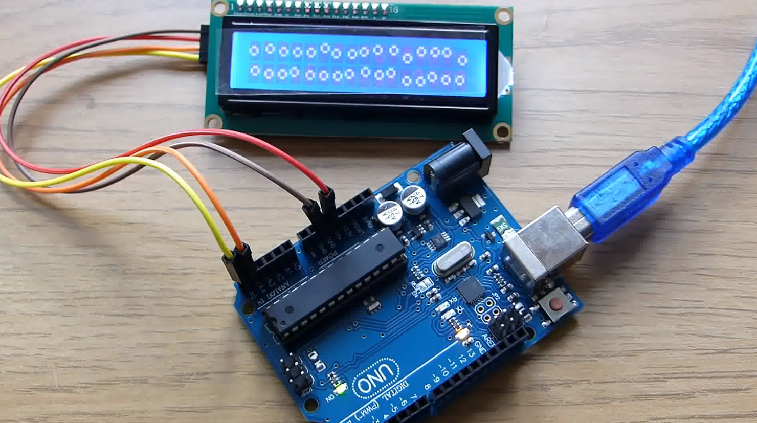
Arduino Lcd I2c Tutorial For Beginners Nerdytechy

Adjustable Timer Circuit Diagram With Relay Output Circuit Diagram Timer Arduino
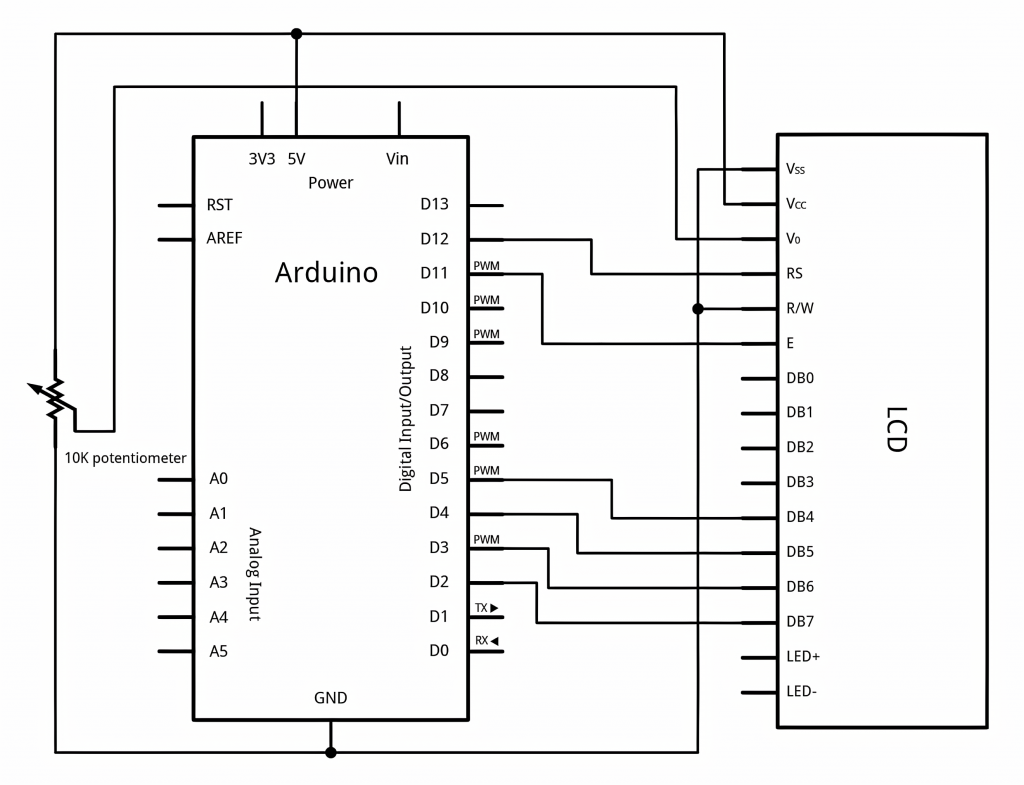
Arduino Lcd I2c Tutorial For Beginners Nerdytechy

Pin On Arduino

I2c Inter Integrated Circuit Is A Short Distance Serial Interface That Requires Only 2 Bus Lines For Data Transfer It Was I Circuit Arduino Arduino Projects
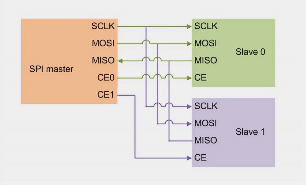
How To Use Spi On Arduino Easy Guide Nerdytechy

Circuit Diagram Of I2c Communication With Pic Microcontroller Pic Microcontroller Microcontrollers Circuit Diagram

Pin On Elektronika
What Is The Difference Between Rs232 And Can Quora

Here S A Resistance Temperature Detector Rtd Interface Circuit That Is Compatible With A Range Of Standard Rtd Sensors Including Pt1 Interface Sensor Circuit
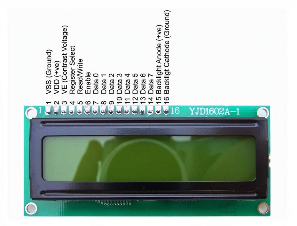
Arduino Lcd I2c Tutorial For Beginners Nerdytechy

Simple Bus Level Shift I2c Mosfet Level Converter Fairchild Bss138 Schematic Electronics Circuit Circuit Application Note

Pin On Electronic Components
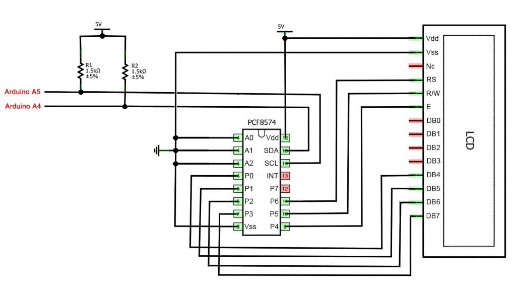
Arduino Lcd I2c Tutorial For Beginners Nerdytechy
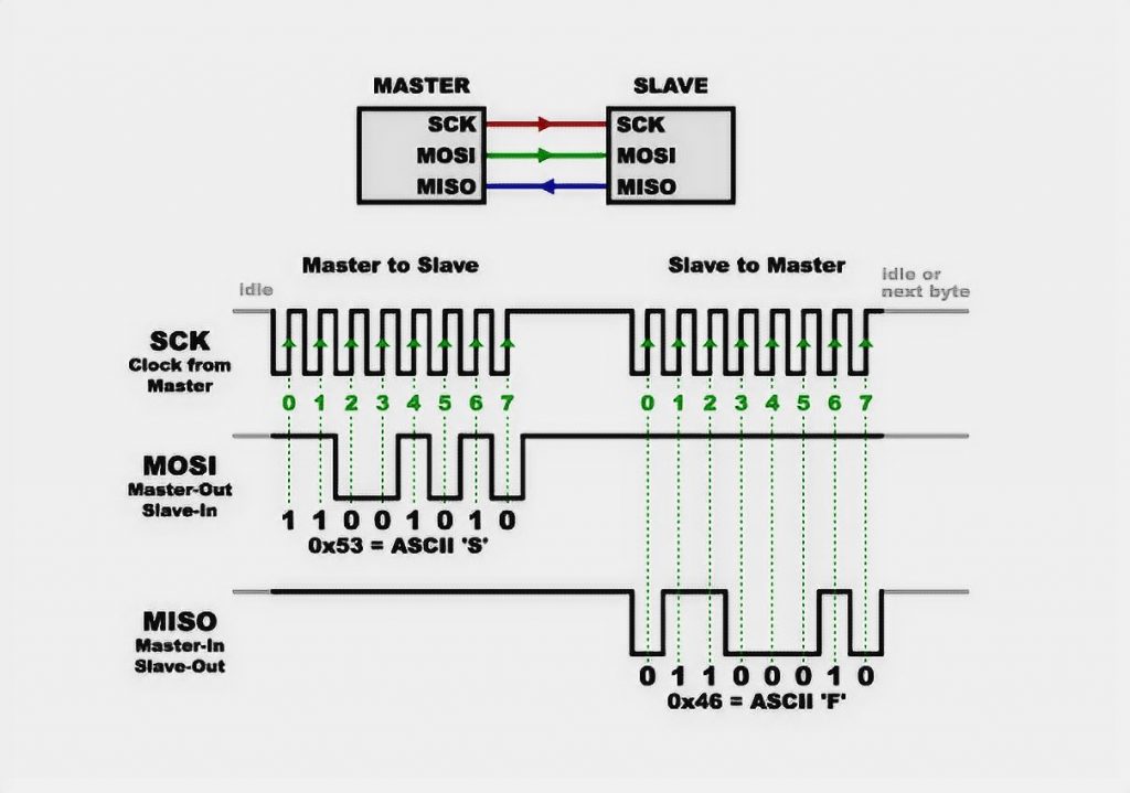
How To Use Spi On Arduino Easy Guide Nerdytechy

Pin On Schematics